Executive SummaryBackground Last Summer (August 2010) TechniCom Group published a report comparing Autodesk Inventor and Dassault Systemes SolidWorks using our Delphi Expert Analysis methodology1 . The results of this report were somewhat controversial; Autodesk Inventor scored better in all fifteen categories considered than did SolidWorks. The scoring for the Delphi Expert report was the result of a very detailed survey of eight expert users of the two systems, four experts for each system. The experts had comparable familiarity with their systems and comparable backgrounds. Readers of that report evidenced hunger for more detailed information, one that might be less sensitive to opinions and be more factual. As a result, TechniCom worked with Autodesk to develop a series of tests between the two systems that might expose the differences between the two systems and perhaps highlight advantages Inventor might have as compared to SolidWorks.
Deciding what to testFirst we had to decide what to test and the scope of the testing. Followers of the mechanical CAD market are no doubt aware of the term Product Lifecycle Management, often designated as PLM. Autodesk’s mechanical philosophy is to eschew developing PLM software in favor of digital prototyping. The term “Digital Prototyping” has led to some confusion in the industry. One clear definition comes from IDC in a paper entitled “Digital Prototyping: Autodesk Strengthens Competitiveness of Worldwide SMB Manufacturers’, published October 2008. This whitepaper differentiates digital prototyping from PLM by noting that “PLM reaches from a product’s cradle to its grave. On the other hand, digital prototyping stops at the completion of the digital product and its engineering bill of materials . . . The beauty of digital prototyping is that designs can be tested out before they go to manufacturing.” Thus, Autodesk’s definition of digital prototyping includes the basic functions of PLM — industrial design, design and engineering, data vaulting, and collaboration, without the post-manufacturing baggage. Autodesk has been carefully steering its Inventor software product development over the past few years to enable workflows that take maximum advantage of seamlessly passing data among its built-in application solutions. Thus, what we see in Inventor today is a careful melding of technologies that Autodesk has acquired or built. Many of these technologies are not available as extra cost add-ons to the base software, but fully included as part of the Inventor software. Some example, of which you will see more later, include mold analysis software, mold base design capabilities, built-in advanced simulation, inherent design automation options, an intelligent part library, built-in engineering calculations, and many others. Not only are these available as an integrated part of Autodesk Inventor, but they are often combined to form workflows that aid in developing the digital engineering models. Thus, when deciding the scope of what to test, we settled on a series of tests that focus on the areas in our Delphi Expert analysis where Inventor rated the highest. These areas include the following: 1. Plastic Part Design 2. Plastic Injection Mold Design 3. Assembly Design and Analysis
Even deciding on these seven areas leaves a great many options to be tested. Autodesk decided on the detailed functions to be tested. Autodesk has specified the seven tests in detail. They are aimed at comparing the two systems ability to perform common, real-world engineering workflows. These tests are not designed to be impartial; they are taken from standard demos used by Autodesk that were designed to represent a series of engineering workflows highlighting Inventor’s digital prototyping capabilities. Most of them, as the users can see below, are aimed at performing a complete design sequence. We have included, in the following seven sections, the details of what we tested, images and videos of the results, what we observed comparing the two systems, and our summary of how well each system was able to perform the desired workflow.
Tests specified by AutodeskAutodesk provided TechniCom with the test definitions including videos of Inventor performing the desired task, starter geometry, related dimensions, and other relevant data, all described below within each test section. TechniCom’s task was to perform the same tests using SolidWorks Premium 2011. Because Autodesk provided much of the model data we were able to focus on the desired workflow details of each test, rather than building geometry. Full disclosure Autodesk paid TechniCom to perform these tests and to document the results in this report. Our approach TechniCom, in collaboration with a Certified SolidWorks Professional (CSWP) performed and analyzed these tests during November and December 2010 using Inventor Professional 2011 and SolidWorks Premium 2011. To make the scope reasonable, we limited each vendor’s software strictly to what was included with the package or third party add-ins that we were able to find and download free of charge. As input, we used the Inventor videos illustrating the work to be performed. We attempted to deliver the same results using SolidWorks Premium 2011, as did Inventor. We are making available to the readers of this report, annotated videos of both Inventor and SolidWorks performing the tests on TechniCom’s blog at www.raykurland.com. Readers wanting to understand how the two products compared have the unique ability to review these videos along with reading our test summaries in this report. Summary of the test resultsIn the first two tests, plastic part design and injection mold design, Inventor clearly outclasses SolidWorks. Whereas Inventor completed all aspects of the test, SolidWorks was unable to complete major portions of the analysis of the part and the mold. Inventor was also able to design the mold significantly faster than SolidWorks due to the inclusion of automated tools for designing the various subsystems of the mold. For the assembly design and analysis test, both systems were able to model the addition of a clevis pin. However, Inventor excelled in its ability to design the correct pin by coupling its engineering calculation library to the potential design. In other words, Inventor helped select the correct pin size because it was able to use its calculations concerning the required. stress that the pin would need to perform correctly. This is subtly different than SolidWorks, which used its library to size the pin, but without taking into account its stress requirements. The SolidWorks approach was to design the pin and then analyze it in an iterative fashion using its built-in FEA solution until the specifications were met. In this case SolidWorks was unable to verify that its built-in FEA solution was correct. A more advanced version of the FEA solver would have been required; concomitant with more advanced engineering skill.
The latest release of SolidWorks added some BIM exchange capabilities, but Inventor’s BIM data transfer capabilities exceeded SolidWorks in key areas important to building designers. These included specifying connection points and component types that are carried over to the BIM-designer’s software. In addition, the mechanical designer using SolidWorks had a more difficult time orientating the model and simplifying a non-native model for export.
Our test of CATIA interoperability and direct modeling on imported models reiterated the widely known issue that SolidWorks does not directly import a native CATIA V5 file, even though both products are part of the same company. Direct modeling was comparable for both Inventor and SolidWorks, with SolidWorks being a little easier to use for the simple direct model changes we made. The SolidWorks drawing output in DWG format produced an incorrect dimension in a scaled view.
For design automation, our tests revealed two weaknesses of SolidWorks. SolidWorks with DriveWorksXpress was not able to automatically scale drawing views to fit a part within the confines of a drawing after the size of the part was changed. Manual intervention was necessary. A second weakness was shown when scaling a copied assembly using 3D curves to define key points as the assembly was copied and scaled to other planes. Inventor was easily able to scale a copied assembly using drive curves; SolidWorks could, but required significant manual effort.
Both systems proved to be comparable in mechatronics where we tested the ability to build wire harnesses using schematic input from electrical software packages, albeit Inventor was able to do so with many fewer interactions.
ConclusionsRay Kurland, President of TechniCom knew that the tests were meant to highlight Inventor strengths, but was surprised that SolidWorks Premium 2011 was, in many tests, not able to do the work without adding pricey third party software. Duplicating Inventor’s capability on these tests with third party products will also make SolidWorks substantially more expensive than Inventor. These seven tests underscore our contention from our previous Delphi Expert Analysis, that Inventor is a mature system that can more than effectively compete with SolidWorks and should definitely be considered for even the most complex situations. The Inventor workflows illustrated in this series of tests are integrated and highly logical, enabling users to accomplish their design goals with minimal effort. Beyond that, we hope to have shown the value of Autodesk’s digital prototyping emphasis, which we expect will continue to evolve even further.
Overall, TechniCom is most impressed with Inventor and the direction Autodesk is taking for the future. To keep abreast with our continued tracking of the industry and our reactions to Autodesk’s direction we advise readers to follow our blog and twitter feeds
Plastic Part DesignThis tests the ability to import surface data from Alias, stitch the skins into a solid body, design the shell the part with a specified wall thickness, part using surfacing and plastic features, import new surfaces and update the model, and perform an injection molding simulation on the part. Autodesk provided us with data files specifying the solid model, IGES and WIRE data files of the surfaces, and three movies depicting the workflow for surface import, engineering design, and simulation and validation.
What’s Important in Plastic Part Design
Observations
Surface ImportInventor was able to import the Alias wire file natively without issue. SolidWorks was unable to import the Alias wire file. Users must first translate Alias data to an IGES file, which is susceptible to translation errors, albeit not in this case. Build the ModelCreating a solid model from imported surfaces and being able to shell the resulting solid are typically the most error-prone steps in the process. Inventor was able to stitch and shell the part with zero errors. The shell was created in one step by defining the variable in the shell dialog box.
SolidWorks was also able to stitch and shell the part with zero errors. Shell creation involved several steps to create and define the variable. Plastic parts are typically designed using a set of standard features such as ribs, bosses, grilles, snap-fits, and lips to name just a few. The MCAD software should assist the user in efficiently modeling these features. Inventor used its plastic features toolset to add the two different types of bosses, a lip feature, and ribs. SolidWorks used plastic features for a majority of the features, although the recessed bosses required for this test first needed to be built manually and then added from the library of custom user features. Simulate and Validate the Part Design
Plastic parts must be checked for potential quality defects prior to committing to the cost of designing and building the mold. In the simulation to evaluate the manufactured quality of the product as-designed, Inventor simulated the injection molding process and uncovered high amounts of shear stress due to the part being too thin. If left uncorrected, this issue would lead to material degradation and molding defects or field failure. Inventor’s built-in mold analysis software also provided more extensive capabilities in terms of material selection and multiple gate analysis.
There are no built-in simulation capabilities within SolidWorks for evaluating the manufactured quality of the product as designed. However, we were able to use a third partner add-in module called SimpoeXpress. This has limited function, but allows for some material selection and a single gate. SolidWorks was able to simulate the molding process but the only result the user received was the filling pattern, which provided limited value. It was unable to identify any quality defects and the user was misled into thinking the design was acceptable. More comprehensive simulation packages are available at a cost of more than $5000. After modifying the 3D CAD model, we reran the simulation to validate the design change. After making the recommended change to the part, Inventor automatically updated the model in the simulation environment; all that was required was to re-run the analysis. SolidWorks automatically updated the geometry but the analysis had to be setup from scratch, including processing parameters, gate location, and material selection.
Summary
Importing the IGES files and creating the plastic part was comparable for both products. While SolidWorks was able to import IGES curves from industrial design software, Inventor was able to directly read Alias (a leading industrial design software package) surface data, an advantage. Both products had excellent capabilities for building specialized plastic features such as the mounting boss and the lip and groove on the connecting halves of the model. Plastic Injection Mold Design
In this section, we test the ability to use the 3D model of the plastic part to create the core and cavity of the mold, design and engineer the multiple components and systems of the mold, and validate the design to ensure it can manufacture high-quality plastic parts. Autodesk provided us with a model of the handle to be molded, detailed specifications for the mold, and three movies of Inventor performing the desired tests showing the workflow for splitting core and cavity, engineering of the mold, and a simulation and validation of the mold.
What’s Important in Plastic Injection Mold Design • Balance of speed in designing the mold while ensuring high quality. • Accurate design of mold components including runners for injecting the plastic materials, cooling of the mold, and ejecting the finished part. • Iteration of the mold design with simulation to arrive at an optimal design.
Splitting the Core and CavityThe desired result was to generate parting surfaces and complete the core and cavity operations Inventor used a mixture of automated and manual patching and runoff surface creation tools. Surfaces for simple holes and profiles were created automatically which increases productivity. Complex patching and runoffs were created using Inventor’s surfacing tools. SolidWorks also assisted the user in splitting the core and cavity with automated and manual tools for defining the parting line and creating patching and runoff surfaces. The two systems are comparable in capability. SolidWorks required a few more menu picks and interactions, but both came up with an acceptable mold core and cavity. SolidWorks generated an odd triangular shape in the area to be removed, but it was temporary and did not affect the final part.
Engineering the MoldThe tasks completed included: designing the runners, adding a submarine gate, inserting a properly sized mold base, inserting a sprue bushing, designing cooling channels, attaching pipe fittings for cooling channels, and adding ejector pins as specified. Inventor completed this task using a built-in workflow for designing injection molds that includes libraries of mold bases and standard components as well as automated design tools for runners, gates, cooling channels, slides, lifters, and ejectors. Automated ejector placement in Inventor (left) vs. manual placement in SolidWorks (right). SolidWorks had no built-in functionality for designing injection molds. All standard components needed to be searched for and brought in from external content centers or supplier websites, a time-consuming process. All modeling was done manually as there are no automated design tools for the various systems of the mold. This made mold design in SolidWorks a tedious and laborintensive process with low user productivity. SolidWorks was able to build the geometry required for the moldbase design, but it was a laborious process. Validating the Mold DesignTo validate the mold design for manufacturability we needed to first determine the optimal molding conditions for the entire system as designed. Next, we performed a filling analysis to determine if the mold, as designed, could completely fill the cavity at acceptable quality. Then, we assessed the location of air traps and weld lines. Lastly, we performed a shrinkage analysis so exact figures could be input for core and cavity sizing rather than manually inputting generic percentages. Inventor includes Autodesk Moldflow simulation built-in to the mold design workflow, which was used to simulate the filling. SummaryAutodesk Inventor provides standard libraries of mold bases and components along with automated tools for splitting the core and cavity and for designing the runners, gates, and cooling and ejection systems. The inclusion of Autodesk Moldflow simulation software directly in the design workflow allows designs to be validated and improved upon until they will optimally manufacture products of the highest quality. SolidWorks includes dedicated functionality for splitting the core and cavity, but that is where the mold design capabilities end. With no automated design tools and no libraries of components, the design of injection molds is entirely manual and inefficient. Without any built-in plastics simulation capabilities, mold designers must purchase 3rd party software, such as Autodesk Moldflow, to validate and optimize their designs to ensure quality. Assembly Design and Analysis
This test focuses on the design of a clevis shear pin and its related holes in this hydraulic clamping assembly. The pin needs to be optimized so that if a failure occurs, the pin fails and not the other components. We’ll seek a factor of safety of 2 for the clevis pin, and 4 for the rest of the assembly. The Clevis Pin shear pin must withstand 250 N force with a factor of safety of 2. The bending force on the pin is important. If it exceeds maximum allowance the pin cannot be removed. The pin should be sized to meet the forces at the designated safety factor and fit within the support structure. The pin should further be selected from a standard library of components and created with the size required. The design calculations should be stored for documentation.
Final assembly, arrow points to clevis pin to be designed. Autodesk provided a Parasolid model of the above assembly and a movie of Inventor performing the design and analysis to select the proper pin to fit within the clevis opening. What’s Important in Assembly Design and Analysis• Select the most appropriate purchasable clevis pin that meets the specifications
Observations
Inventor executes all of the steps (make the hole, insert the pin, perform the engineering calculation) required within one command (feature). SolidWorks uses separate commands for each of the three key steps. Both Inventor and SolidWorks seem to have an equally robust clevis pin library, and automatic sizing capability. The engineering calculation is the large differentiator in the example. Both Inventor and SolidWorks offer integrated finite-element analysis (FEA). However, using FEA methods for this kind of problem is a questionable strategy. Autodesk prompted the user to determine the correct pin size by using its engineering calculations. SolidWorks does not provide this kind of functionality. SolidWorks’ concept was to have the designer select the pin size and then perform an FEA analysis in an iterative fashion to arrive at the correct sizing. SolidWorks was able to use its own no-charge Simulation Xpress to perform the FEA analysis. SolidWorks Simulation Xpress is a first-pass basic stress analysis tool that comes with every SolidWorks Standard and Professional software package, offering limited FEA functionality. Design Accelerator in Inventor (left) and SimulationXpress environment in SolidWorks (right). Standard engineering calculations (analytical methods) exist for this situation, making FEA methods unnecessary/overkill. The FEA boundary conditions necessary for this case present a convergence issue (singularity) for most solvers. This increases the expertise required to verify the accuracy of this FEA study with any level of certainty. Some FEA programs will simply never reach a reliable result for this case. This is typically referred to as a divergent case. SolidWorks Simulation Xpress did not allow us to individually manipulate the mesh to test for convergence. SummaryBoth Autodesk Inventor and SolidWorks can solve this problem; however there are important differences in the steps required to complete the exercise and the confidence in the engineering optimization. Inventor executed all of the steps within one command sequence. SolidWorks uses separate commands for each of the three key steps. Both Inventor and SolidWorks seem to have an equally robust clevis pin library, and automatic sizing capability. Inventor users have the ability to leverage standard engineering calculations shown below which are included in design accelerator tools. In this test we examine the clevis pin generator. The same concept applies to bolts, bolts, frames, shafts, gears, bearings, belts, chains, keyways, cams, splines, o-rings, and springs. Inventor does not require the user to know or learn the engineering equations; the software does it for you. In the case of using FEA, the engineer must be concerned with the accuracy (error) inherent to FEA methods, necessitating a higher skill set, and certainly more time. Inventor’s automation of standard engineering calculations provided a better solution and reduced design time. Exporting BIM Ready ModelsIn this test, we started with a complex assembly that had already been designed in the mechanical system. The goal was to export a simplified version of the assembly for inclusion in Autodesk Revit software (BIM software). The software should allow the user to reduce the level of detail in the exported file to protect proprietary design information, to indicate to the BIM software the category (window, door, HVAC, etc.) of the exported data, to provide types and locations for plumbing and electrical connections, and to be able to control the orientation of the exported part or assembly.
Orientation for ImportThe second step was to orient the part properly for use in BIM software. Ensuring that models come in with the correct orientation removes the frustrating process of reorienting every time the product is inserted into a design. Inventor allows the user to create and assign a custom local coordinate system that can be specified on export thus eliminating this issue. SolidWorks can create a custom user coordinate system (UCS), but cannot use it when exporting IFC files (a BIM standard file format). A new assembly needs to be created with the product placed in the correct orientation. This workaround requires additional time to create the new assembly and creates additional data to manage. Define Connection PointsThe third step was to define connection points to the assembly with sizing and connection attributes. Mechanical, electrical, and plumping (MEP) engineers need to know the location, size, and type of connections required for the product when designing piping or wiring for the building. Inventor allows the user to specify the location of connections along with information about pipe size, wiring, connection method, system type (i.e. hot water/cold water/120v/240v/etc.), and flow direction. SolidWorks is unable to assign connection properties, instead requiring the data to be manually communicated, a minimally acceptable alternative.
Data ExportThe fourth step was to export the assembly to a file format that can be read into BIM software with the necessary attributes assigned. Inventor exports file formats that can be directly read into Revit or AutoCAD and can be included in Building Information Models. Component types assigned in Inventor were carried over so no additional categorization was required. Additional properties are carried over, such as weight, size, and appearance. SolidWorks exports IFC 2×3 neutral format files that can also be directly read into Revit or AutoCAD. Component type can be assigned on export and are carried over into Revit. BIM designers are required to manually assign additional properties. Interoperability and Direct ModelingTo examine interoperability, we tested the capabilities of the software by importing a CATIA part, modifying the imported part, and creating and validating the accuracy of a DWG drawing of the part for communication with vendors. View of the bell housing used in this exercise. Autodesk provided a video of Inventor being put through this exercise, the bell housing in CATIA format and the bell housing in IGES format. What’s Important in Interoperability • Directly reading the other systems data directly – in this case CATIA V5- rather than performing a multi-step and potentially error prone process of intermediate data conversion .• Easily share design data with customers, vendors, suppliers, and other departments using different CAD systems. • Reading and writing DWG files for production, and publishing designs in formats that customers can use in their own applications. Importing CATIA PartThe desired result of this test was to import a CATIA V5 model into the software. Autodesk Inventor read the CATIA data directly and was able to open the model with no issue. SolidWorks was unable to read the native CATIA V5 model. Third party products are available that offer direct CATIA – SolidWorks translation. As a workaround for this workflow test, the IGES file was used in later tests and successfully imported into SolidWorks. The need to convert each CATIA V5 file to the IGES format may be a major issue for automotive and aerospace suppliers and OEMs since there are many companies involved that require data in native CATIA format!
In the video, Inventor made the necessary modifications using the free Inventor Fusion Technology Preview labs application. The changes were made successfully and then Change Manager was used to update the dumb solid in Inventor. SolidWorks had no problem with the direct modification of the imported part. Feature recognition capabilities were used to modify the plates and the holes as required. In this case it was easier than Inventor, which required back and forth interaction with Inventor Fusion. Creating DWG Drawing Next, each spftware system was used to create a drawing in DWG format, make a change to the 3D model and update the DWG. Inventor created the drawing in DWG format – no translation was required. The file was opened in AutoCAD and presented exactly as it had been in Inventor. After making a change to the 3D model in Inventor, the DWG version of the drawing updated automatically. SolidWorks is able to create DWG files for export to vendors. However, these DWG files lack the ability to be fully associative with the SolidWorks 3D model. This means an additional change to the SolidWorks 3D model requires that a new DWG file be created. The exported SolidWorks DWG was opened in both AutoCAD and Dassault DraftSight. In both AutoCAD and Dassault DraftSight, the SolidWorks DWG produced a dimension that showed as 64mm instead of the correct 32mm. SummaryAutodesk Inventor easily imported the CATIA V5 file. Working with imported data requires the direct modeling tools found in Inventor Fusion Technology Preview to make changes. Creating a fully associative drawing in DWG format using Inventor requires no additional effort since Inventor uses native DWG as the file type for drawings created from the 3D model. SolidWorks is also able to import IGES files and export a DWG drawing format but has no support for CATIA V5 files, which must be translated into a neutral file format like IGES before use. File translations introduce complexity and the potential for errors. Once called up in SolidWorks, the program has tools for modifying non-native 3D geometry with several functions like feature recognition and move face. Last, in SolidWorks, DWG drawings are not associative to the 3D model and may require a significant amount of time and effort to create new DWG for each change of the 3D SolidWorks model. More time may also be needed to clean up any DWG drawing export errors that occur prior to sending them to customers and vendors. Though the SolidWorks DWG associativity did not work in this test on TechniCom’s version of SolidWorks 2011, SolidWorks has supported this capability in past releases and it may work in other installations. Design AutomationThis test looks at a simplified automation examples, yet in the time allotted provides a glimpse of this capability in both products .• Create a simple piece of stock lumber (2×4 board) and examine how a user can make that same part file represent several variations of lumber that could be used in a project • Automate the variation of individual drawing views, scales, and annotations. • Automate assembly variations that vary by size and position. Autodesk provided us with three movies showing Inventor completing the tasks. They also provided three STEP files of the frame, the assembly, and the curves to follow for the frame assembly resizing. What’s Important for Design Automation • Engineers can capture design intelligence by using rules to embed design intelligence into parts, assemblies, and even drawings • Such design intelligence, in the case where repetitive designs or portions of repetitive designs are used, can radically reduce design time and produce more repeatable results. • What techniques are used to build the design intelligence (often programmatic) • How easy is it used to create new designs once the rules have been built • How such design intelligence is accessible and how it can be maintained in the future.
SolidWorks has some of the same capabilities built into the modeler. It can handle configuring a part when placed into an assembly, but updating it in the part model on the fly is not possible. It was also able to create the multiple configurations of an assembly – although it required more steps. Without using extra cost third party software, SolidWorks is unable to automate the creation of drawings for part families, which requires users to create a drawing for each instance of the family. For the stock lumber workflow, both Inventor and SolidWorks were able to capture all the variations within a single part file. A family of parts or assemblies also requires a family of drawings to document their design intent. Recreating essentially the same drawing, which only varies by a few critical dimensions wastes time and effort. Inventor allows the user to easily automate drawings using iLogic functionality. Inventor drawings can be set up to automatically vary view placement, scale, and annotations for a family of parts or assemblies. SolidWorks, without extra cost third party software, is unable to automate the creation of drawings for part families. For the frame variation example, Inventor allows the user to automate complete assemblies that vary along specified paths. SolidWorks was able to manually model the frames along a path, but took substantially longer. Summary SolidWorks has some of the same capabilities built into the core modeling system and by using DriveWorksXpress, a 3rd party add-in delivered with SolidWorks. It can handle configuring a part when placed into an assembly, but updating it in the part model on the fly is not possible. It was able to create the multiple configurations of an assembly – although it required more steps than Inventor to achieve the same solution. SolidWorks Premium was unable to automate the creation of drawings for part families, which requires users to go through the manual process of creating a drawing for each instance of the family. SolidWorks’ third party partner, DriveWorks, offers software that can perform this process, although at additional cost. The no-charge version was not able to control the final drawings, as desired. We did not evaluate DriveWorks, although the extra cost versions of DriveWorks Solo and DriveWorks Pro appear able to perform this task, again, at added cost. Autodesk Inventor includes iLogic and iCopy technologies that use rules to control the parameters of the part, assembly, or drawing and these capabilities were used to complete this test. Inventor created the lumber workflow, the frame resizing and the drawing scaling without flaws
MechatronicsThis tests the ability of the mechanical CAD system (MCAD) to leverage data from an electrical CAD system (ECAD). The ECAD system specifies the appropriate connectors, wires, and their connection points while the MCAD system specifies the physical location of those wires and connectors within a product. Autodesk supplied us with an Inventor video of their solution, a net list in Excel format, a STEP file of the enclosure assembly, and a schematic drawing (.dwg) of the connections. What’s Important in Mechatronics Design• Leverage the data stored in schematic drawing files to design wire harnesses in the mechanical system. Such data can be stored exported from an electrical design file using various techniques. At its most basic, the electrical design software sends a net list to the mechanical package containing connector information for each wire, wire types, and a list of pin-to-pin connections. • Generate correct wire lengths • Generate output to enable manufacturing of the wire harness • Not tested were two-way associativity between the electrical and mechanical software, nor were any tests designed to simulate electromechanical interconnections such as activating switches or sensors based on mechanical actions. Observations For this test, on the AutoCAD side, AutoCAD Electrical exports an XML file to Inventor. Inventor reads this file and generates the 3D wiring and, under user control, assigns wires to cables. It can then generates wire lengths, a flat wire harness diagram and a pin board for manufacturing. Inventor opens the 3D model and then the xml file of the net-list from AutoCAD Electrical with these tips and tricks. This designates the pin-to-pin connections where the wires are to be placed. Different then SolidWorks,rtant in Mechatronics Design
Related Autocad Pages
After the import, the imported wires appear as direct point-to-point connections between the pins without using any harnesses. 19 wires were imported and identified as un-routed. Then Inventor asks for an auto-route of all un-routed wires. It then places all 19 wires into the predesigned harness, we guess by using closest entry and exit points. Then Inventor builds (and reports) a pin board payout of the harness showing the 3D derived wire lengths. SolidWorks takes a slightly different, albeit very similar approach. After importing the net-list, the operator builds a 3D representation of the harness and then places the wires into the harness, with the software computing the wire lengths. This took more manual interaction than the Inventor solution, but yielded the same end result. Summary The two software packages (Inventor and SolidWorks) are comparable. Inventor has a tight connection to AutoCAD Electrical with the xml file transfer. SolidWorks has similar tight coupling with some third party software such as Zuken’s E3. Both systems use added cost electrical software to generate the net-list. SolidWorks was not able to read the AutoCAD Electrical generated xml list, and instead used an Excel file with similar data that needed manual cleanup in Excel. It appears that there are a few more interactions with SolidWorks, but this may be due to the operator-preferred method. Both systems effectively produced the required output. There appears to be no real operational advantage to either package when used with tightly integrated electrical schematics software. Since AutoCAD Electrical is one of the most widely used electrical schematic packages, the advantage goes to Inventor.
The post Autodesk Inventor Professional Tutorial And Testing appeared first on . from http://www.cad-portal.com/autodesk-inventor-professional-tutorial-testing/
0 Comments
Autodesk Product Data Management: A CAD Perspective
Autodesk Product Data Management solutions prove to be easy and straightforward to use, and also promise to considerably increase user productivity during product development. This report reviews Autodesk’s Product Data Management Systems from a CAD Designer point of view. During the process of our review we collected many images of the software functions. We have placed these images, most of which are not included in this paper because of brevity, on our web site along with explanations. AutoCAD Improvements paper can be found here Highlights of the Autodesk PDM productsData management allows Engineering to more easily share and secure data with a formal Engineering Change Order process which can be monitored and tracked. Raymond Kurland of TechniCom, the author of this paper, spent several days at Manufacturing Solutions Division (MSD) headquarters in Tualatin, Oregon in mid August, 2006, focusing on Autodesk’s Data Management Solutions and their interaction with Autodesk Inventor. Ray met with Autodesk management and technical experts, the goal being to develop this paper summarizing the connection between Autodesk Inventor, Vault, and Productstream, what they provided for users, and how easy or hard they were to use. Ray met with Eamon O’Gorman, Product Manager for the Data Management Products as well as several executives to get their perspective on the technology and where it is headed. O’Gorman focuses primarily on the requirements for these products, which include Vault, Productstream, and Streamline. This paper summarizes the most important functions of Vault and Productstream, two of the major components of Autodesk’s PDM software and why they are important for prospective users. Autodesk sponsored this paper and minimally edited the final version. The impressions and conclusions are solely those of the author, an independent analyst and consultant in the CAD/CAM/CAE/PDM industry. Manage Work-in-Progress Design with Autodesk VaultMaximize return on your company’s investment in design data by driving design reuse with Autodesk Vault functionality. A centralized data management application that securely stores and manages design data, Autodesk Vault is included at no additional cost with all Autodesk manufacturing design software and AutoCAD ( coupons and discounts are here ) customers signed up for the subscription service. Tightly integrated with each design application, Autodesk Vault organizes all engineering data in a centralized location and reduces the time needed to find, reference, and reuse design data. The graphical UI (User Interface) offers CAD users an intuitive way to access and manage their data. As product designs evolve, versionmanagement features in Autodesk Vault provide protection from unintentional overwriting of good designs. In addition, users can save hours of valuable design time with the powerful copy design capabilities that maximizes reuse of existing designs and reduces the time required to start a new design. See : Autocad Tips And Tricks For Beginners for more ideas
Automate Release Management with Autodesk ProductstreamMaintaining control of the design data until it goes into production proves to be a major factor in getting products to market faster. Obstacles to increasing productivity include changes made to drawings and models without your knowledge, out-of-date bills of materials (BOMs), and trouble sharing design information. Autodesk Productstream automates the release-management process by managing engineering changes and bills of materials (BOMs), which allows engineering departments to maintain control over the design data after release to adjacent departments. Automating this process helps reduce costly errors and delays by minimizing manual data entry so that design changes are communicated directly back to engineering and correct parts are ordered or manufactured for a specific design. Engineering can more easily share design information knowing released information is secure and changes cannot be made without implementation of a formal engineering change order (ECO). In addition to automating release management and tracking the change order process, Autodesk Productstream manages bills of materials and enables the sharing of valuable design data with users outside engineering and applications such as enterprise resource planning (ERP) and material requirements planning (MRP) systems, as illustrated in the image below, provided by Autodesk.
It’s about the process. The goal is to help customers bring standard products with options to market faster with less expense to have an advantage over the competition while providing value to the end customer. Increase Collaboration with Autodesk StreamlineEfficient sharing of designs is crucial for maximum project visibility and collaboration. Autodesk Streamline provides an on-demand collaborative project management solution that enables users to connect, share, and collaborate with external team members, all at minimal complexity and cost. By providing a single location to securely access shared files and collaboration tools, Autodesk Streamline makes up-to-date design information available to customers and suppliers anywhere. Share Designs with Autodesk DWFThe compact and easy-to-use Autodesk DWF file format for sharing designs offers a free and simple way for team members to publish any Autodesk design to DWF. The free Autodesk DWF Viewer allows anyone, including customers and suppliers, to easily view and print even the most complex 2D and 3D designs. Autodesk Design Review, available for a modest cost and included free with each copy of Productstream, accelerates the design review process by providing an all-digital way to review, mark up, and revise designs without the original design creation software. Most Autodesk CAD applications include Vault at no extra charge. As you will see by the end of this discussion, it is therefore a no-brainer to use Vault instead of a file based system. We recommend that all users immediately begin the evaluation process to install Other Autodesk ProductsHere are few more write ups we have made about autodesk and autoCAD products
ConclusionsUse Autodesk Vault. The benefits are enormous (as you will see from the following discussion), the risk minimal, and only a nominal initial cost for help in getting started. Here are some more details on why we came to this conclusion.
When you are ready for the next step, Autodesk offers the Productstream release management system. This includes Bill of Material Management, Release Management and Change Management. While all of these can be installed and operational at once, it might be easier to take an incremental implementation approach, recommended by Autodesk. Designed to go beyond the task of maintaining the correct version, for which it requires Vault, Productstream offers many additional advantages. Only a few of these follow. Users are sure to find many more.
ECOs.
Description of the functionality of Autodesk Vault and ProductstreamIn case these descriptions whet your appetite for seeing more details of the software, contact your appropriate Autodesk representative or reseller. Autodesk contact information is at the end of this paper. You can also contact the author with feedback at [email protected]. Productstream provides an out-of-thebox ready solution by supporting a limited number of standard operating workflows, which can be modified. TechniCom’s descriptions and conclusions derive from discussions and demonstrations with Autodesk technical personnel and executives. We were able to interact closely during demonstrations and discussions of the functions discussed below. Since this is a very visual business, a few screen images are included below to expand on the text. This should enable the reader of this paper to obtain an introductory “feel” for the functions. The Autodesk PDM product family consists of Vault, Productstream and Streamline. These are buttressed by the ability to view Inventor and other Autodesk data files using the DWF file format, including DWF viewer and the new Design Review , for more see our Guide to Selecting a Mechanical CAD System for Small and Medium Businesses Use Vault for work-in-process data managementVault offers a work-in-process Product Data Management System capable of automatically producing versioning, primarily controlling file-oriented data. As you will see by the end of this discussion, it is therefore a no-brainer to use Vault instead of a file based system. We recommend that all users immediately begin the evaluation process to install and use Autodesk Vault. The benefits are enormous (as you will see from the following discussion), the risk minimal, and only a nominal initial cost for help is needed to get started. Managing the myriad file types created by Inventor is a complex task. The file types include .IPT (part files), .IAM (assembly files), .IDW (drawing files), and .IPN (exploded assembly files). Why worry about where they are located and which have changed? Vault does all that for you. Productstream adds additional capability to Autodesk VaultProductstream adds additional capability to Autodesk Vault, most notably, bill-of-material management, release management and change management. As opposed to versioning, it produces revisions and operates on objects called items. A typical work flow might be as follows. For a customer operating in the vault environment, when the work in progress is considered complete and ready for release, it would be released into the Productstream environment where changes and revisions would be managed. Productstream has a considerable amount of workflow capability. It is however, not a completely customizable system, but one oriented toward specific standard operating procedures, which can be modified. By doing so, Productstream provides a more out-ofthe-box ready solution. Productstream requires Vault as a pre-requisite. Installing Vault requires an SQL server, the Microsoft product for database management. If not installed previously, installing Productstream automatically installs one for you. Productstream not only stores data from Inventor, it stores any file format such as that from Microsoft Office. Without understanding the content, it can manage versions for any file. In addition, Productstream understands the product structure of SolidWorks and Pro/Engineer by integrating directly to these applications using their APIs. Of course, CAD authors have access to their data. But non-authors can access Productstream data from other areas of the company, such as manufacturing, purchasing, and sales, etc. Such access is granted through rich clients called Creator, Reviewer, and the browser-based Explorer. These are chargeable items ranging from $1,795 per network license for Autodesk Productstream Creator down to as low as $200 for Autodesk Productstream Explorer. Streamline, the third product, is primarily a host-based product, oriented towards allowing supplier and customer access for those companies that are not part of the originating enterprise for the data. It acts as a security barrier when data is uploaded; customers can only view that data for which they have access. Built-in security provides encryption for uploading data and storage and a permissions matrix. Streamline also provides an activity log, performance monitoring information, and the ability to extensively search for data, including internal access to metadata (additional descriptive data) and content data within, for instance, drawings. Data is “pushed” (manually uploaded) from Productstream to Streamline, or this process could be automated with a minimal amount of Autodesk services consulting.
Using Productstream to complete the ECOProductstream helps manage the ECO through its approval, review, and modifications stages. Image 8 – The ECO Routing tab defines The revision we made above primarily centered around CAD, creating and controlling the parts and assemblies to build a new design. Thus, we used the Autodesk Vault work-inprocess functions. Now, with the CAD design complete, we need to move into the release phase. Our next tasks, thus involve administration of the BOM, release management, and change management, all part of Productstream. Assigning item numbersFirst, we execute an “assign item” wizard function to change from the engineering part numbers to item numbers. The system automatically assigns item numbers that meet company standards sequentially or using a mapped numbering scheme. For instance, in our case, this was ASKA XXXX, with the four-digit number sequentially numbered by the system for every new item. Alternatively, item numbers can be derived from file names. We call these item numbers rather than part numbers, because items may include not only parts, but other objects in the bill-of-material besides in-house manufactured parts, such as electronic documents, purchased parts, specifications, etc. Changing from a part number to an item number still retains all the CAD part relationships; the CAD files are now attached to the item. To complete the engineering change for our clamping fixture, we have design work remaining beyond the geometric CAD design — performing an FEA analysis, adding cable ties, and the approval and release of the design. The following steps now become more process-centric, rather than CAD-centric, but are key steps in completing the design process. Sending automated notificationsIn each case where we changed the state of the ECO (for instance, from in-process to design complete) or initiate ECOs, the system initiates and sends e-mail notifications to the appropriate parties, as controlled by routing information previously defined during the creation of a new user, by the administrator.
who participates in the ECO process and what roles they play. Multiple routings can be created to define different processes. The ECO Status Tab (shown here) shows the workflow process. The yellow box indicates the current step. Reviewing and marking up the ECOTypically, the reviewer would work with a DWF file, adding suggestions for changes, as shown in Image 9. Editing the ECO allowed us to access the proposed design using Autodesk’s design review capability (Design Review 2007), included with Productstream. Markups are stored as part of the ECO, retaining a history of the design. At any stage of the ECO, we are able to access the markup. The ECO moves through a series of stages TechniCom, Inc. – 970 Clifton Avenue – Clifton, NJ 07013 USA (973) 470 9110 – http://www.technicom.comThe post Autodesk Products – A CAD Perspective appeared first on . from http://www.cad-portal.com/autodesk-products-cad-perspective/ IntroductionThis paper is a follow on and update of TechniCom’s previous paper published in February 2005. In that paper we discussed “Selecting a CAD/CAM/CAE/PDM system” and noted that selecting such a system is no easy task. Today, years later it is still no easy task to select a comprehensive engineering and product development system, yet it is crucial to the success of ANY business, be it small or large. Our goal with this paper is to help people make better decisions when selecting software solutions to improve product development and engineering performance. This paper can provide you with a logical and orderly approach, which, if followed, will allow you to select the proper 3D mechanical Computer Aided Design (CAD) system for your company. In this paper, different than many others we have seen, we provide guidance for mid-sized businesses rather than large-scale enterprises. We have also provided you a link to all the top AutoCAD deals and promotions which we update every month for all our users so please visit this before buying any Autodesk products In many areas of this paper we stress the importance of making strategic decisions, both short-term and long-term. Readers should keep this in mind. Any decision making tool, be it for product development or business strategy, is only as good as long as it fits the company strategy and directions. We repeat, a tool that seems technologically advanced but does not fit the company needs cannot succeed. We will explore this further, a bit later. This paper is sponsored (partially paid for) by PTC. We agreed to write it because that PTC assured us that it would be completely unbiased -and they have upheld this agreement. Why would they do so? Because they feel comfortable that small and medium business customers evaluating such systems will often decide upon PTC offerings, providing that customers have a rational approach to making such a decision. This paper provides such a rational approach. PTC and the authors know that no single solution is right for all customers.
Executive SummaryThis paper defines a well thought out, logical and orderly process to select a new CAD system. We focus our energy in this report on the process of justifying a new system and making decisions based on business needs first, then developing the technical and functional requirements to support those business needs. The best we can do in a paper of this length is to provide overview guidance to customers making such a decision. We have tried to distill our years of expertise into this paper. We hope you will find the methodologies presented by the author clear and usable. First we discuss a CAD system, why it is important and why a company might consider switching to a new one. Then we launch into the how-to of going about the selection and many things to consider along the way. Over the years, we have observed and been involved with the complexities of such a decision. We can only provide you with our sage advice and recommendations of a process to follow. It is up to you to work with our recommendations and bend them to fit your company. Notice I said, bend, not discard. We take you from the early decision stage, show you how to get started in organizing for the process, and guide you through the various stages. The process follows a suggested path to develop requirements in order to judge the software that best fits your needs. We suggest
the development of management requirements, leading to functional requirements, then to technical requirements, and give guidance on how to work with vendors to make the final decision. We conclude with advice on what such a system should cost and some suggestions for implementation. The appendix contains some interesting advice on a technique for evaluating vendor proposals. Good luck with your decision and remember, “Fortune usually smiles on the well prepared.” The Selection Process Defining a CAD systemFirst let’s quibble about what to call a CAD system. For our purposes, we are discussing a mechanical engineering design system. Such a system allows designers, engineers, and others to design mechanical parts and assemblies (objects or models) in 3D, to document them with 2D drawings, to analyze basic properties of the objects, and to share these objects with others during the design process. In addition, there is often a need for specialized analyses, such as FEA, mechanism, plastics, composites, visualization, and other types. To optimize its effectiveness, some type of workgroup data management allows users to store and access the data in various ways that allows them to find data they need, re-use existing designs, and collaborate with others while protecting key intellectual property (IP). We differentiate workgroup data management from another commonly used term called product lifecycle management (PLM), a more encompassing and vastly more complex technology. For this paper, workgroup data management encompasses those activities within the engineering – design department until the product is released to production. At that time, many companies will then transfer overall control of the product data to a PLM or enterprise resource planning (ERP) system. So, for the purpose of this discussion, a CAD system shall include 3D and 2D design, inherent analysis, connection to specialized analysis, an integrated CAM system, and a workgroup product data management (PDM) system. If your funding and business objectives are primarily engineering driven, then you should give more weight to CAD. If your company intends to perform less direct engineering and instead make more use of design partners and outsourcing, then you might want to consider a solution that is lighter on CAD and more focused on collaboration using a PLM solution. For the purposes of this paper, we assume the reader’s objectives are primarily engineering driven and thus in need of a CAD system. Why consider a new CAD system? The continuing onrush of both new hardware and software technology during the last few years, along with the pervasive reach of the Internet provides a unique opportunity to use such a CAD system such as Autocad 360 as the fundamental basis to greatly improve how your company operates. The good news is that such CAD systems today offer enormous power at very reasonable costs. ( for example Autodesk Sketchbook Pro Full Version ) However, CAD systems now reach into many more corners of a company, and as such need careful planning.
A mechanical CAD system is the most important tool of product development. Properly implemented, a CAD system supports the business plans. If a modern CAD system is integral to your company’s future product development, then a careful rational decision must be made that does its utmost to insure that such a system meets both your current and future needs. time, CAD systems were the sole domain of engineering, for use in developing and documenting new products. The other departments, such as manufacturing, testing, procurement, and suppliers, received this data and used it and modified it independently of the original data. Alas, if you couldn’t read the data, you needed to rebuild it in whatever format pleased you. In fact, this mirrored the way companies worked in the good old days of slow speed, paper based systems. In the last decade many forces have changed the way we need to work today. Among these are the need for speed in bringing products to market; the need for world class quality; the requirement to operate in a global economy where customers, vendors, and even engineering can be anywhere in the world; and cost – where customers can compare prices anywhere in the world by simply browsing the Internet. Successful product development in today’s global market requires a comprehensive strategy for your engineering and product development system. In the following sections we discuss how to determine if you need a new system. Chief among the questions you must ask yourself are: “When did you last make a major change or update your CAD software? Was it within the last 3 -5 years?” This seems like a short time, but consider that in those 5 years computers have advanced 100 fold in speed and CAD software has often seen five releases of the products. If you agree that the primary tool supporting your product development is important in keeping your company competitive, then it’s time to re-examine this tool, because a mechanical CAD system is the most important tool of product development. Notice that I said a tool — this is important. It is a tool, but only a tool. A business must focus on its business; it needs to determine what the proper business process is. Then it must consider the tool to meet the process and requirements. It’s not about strategy; it’s about the business of running the business. A well-implemented tool will support the business plans. This is the fundamental message of this paper. For smaller companies, selecting the right solution can be difficult due to limited resources available for the evaluation process. A structured, well thought out process is critical to these smaller businesses. Instead, in many cases, selecting a PLM system tends to be done at too low a level, with poor consideration of company strategic issues, with little understanding of the product development environment and any proposed improvement, and with little idea of expected ROI or metrics. Is this a problem? Yes! If such a system is integral to your company’s future product development, then a careful rational decision must be made that does its utmost to ensure that such a system meets both your current and future needs. A rigorous technique to select a CAD systemTo address the challenge of selecting a new CAD system, TechniCom, in this paper, describes a rational, well-organized approach for a CAD system selection process. It all starts with the business objectives in mind, starting with a determination of whether a new system is warranted or not. This encourages a business case that carefully ties the software strategy to the strategy of the business as a whole. Without this business alignment, the selection process will likely be focused strictly on the technical merits of the software system and disregard evaluation criteria that are critical to the successful implementation (and return on investment) of the PLM solution. Aligning the selection process to the business needs will avoid focusing strictly on the technical merits of the software system. A CAD system can provide a tremendous boost to the business. These steps can ensure that the system achieves your desired goals!
After determining the need and building the business case for the new solution, the author recommends a number of steps to organize and conduct the evaluation process. Assembling the proper team for the selection is an important step, including the development of a cross-functional team and an executive steering committee to drive the process. This team will quantify the company management requirements, functional requirements, technical requirements, and integration requirements. Then this team will drive the process to select a vendor partner and a solution based on these requirements. The paper further identifies a process to evaluate potential vendor partners, including the importance of the vendors’ long-term strategy in addition to current offerings. The evaluation should include an assessment of the vendor’s ability to support the company during the implementation and beyond, including an understanding of design strategy of the company and the ecosystem of partners and solutions that are aligned with the potential software vendor. Finally, the paper identifies a number of potential solution providers and offers some advice on how much a company should plan to spend on a solution of this kind to help ensure a realistic cost for the business case. Selecting a CAD system is an important process, and one that can provide a tremendous boost to the business if done correctly. The steps in this paper are designed to ensure that the system selected can be readily implemented to achieve business value, and try to eliminate misconceptions, poor evaluations, and inherent biases that could lead to late surprises in the implementation or use of the solution. By following these steps, companies can be comfortable that they will be able to achieve the top-line growth and Improvements as they seek from a new CAD solution. Selection technique summary
Setting the stage for getting startedAs consultants and industry pundits who have observed and been involved with many such decisions, we know selecting a new CAD system is a difficult process. The bigger and more complicated the company, the more difficult it seems to be; conversely, smaller companies have fewer technical resources. CAD systems today offer enormous power at very reasonable costs because of advancing CAD: a fundamental capability enabling modern product development. Today’s computer and networking technology allows CAD systems to reach into many more corners of a company, and need careful planning. If you answer “No” to any of these questions you are operating with a deficient CAD or product development system. hardware and software. Precisely because of this, CAD systems reach into many areas of a company and are no longer thought of as just engineering systems, but more as a fundamental capability enabling modern product development. While promising to transform product development, a CAD system must both fit the company environment and allow for a re-thinking about or a transformation of product development processes. The benefits should greatly outweigh the costs and disruption to your operations while changing to a more modern system. Readers who follow the techniques suggested in this paper will be rewarded with a “best fit” solution. 1. Determine if you need a new systemAnswer these questions to see if you need to change or improve:
If you answered “No” to any of these questions you are operating with a deficient CAD or product development system. We suggest that you read through the following steps carefully to determine whether to improve what you have or to change systems and what benefits you can expect. Remember this during the entire project: It’s a business decision, not a technical decision! Make sure the vendor’s references are similar to your company size, and understand how much time and money their implementation cost. It’s a business decision, not a technical decision! You need to develop a business case for upgrading or replacing the existing CAD system. In order to do so, you will need to map how well the existing system fulfills your business plan. What are the gaps between what you want to accomplish as a business and what the existing systems are able to support? Are you paying too much for support of point solutions or custom systems? Do you have the integrated solution that your business demands? How can you improve your design processes with a modern CAD system? Most companies that have not invested in the new generation of solutions for developing and engineering products suffer from inefficient and non-integrated systems. For you to operate as a leading company you will need to make the evolution from standalone tools to integrated suites. For you to properly plan (and justify) your efforts you need to determine where the gaps lie. These are the businesslevel gaps, and should be reflected in business level metrics to support your new business strategy. Once this is done, you can specify the fundamental requirements for new system that fills those gaps and can grow for the future. Select a cross functional teamA good evaluation is based on a strong plan and a strong team. Understand in advance the approach that you will take to the evaluation, the selection of the new system, and the approval of the new system. 2. Organize the EvaluationYour system will touch many aspects of your business. New approaches to developing products demand a much broader level of participation than past approaches. Make sure your team has representatives from Engineering, Product Management, and the Program Office (if you have one). But also include Procurement and Manufacturing representation. Also, consider including Sales if your business involves any make to order (MTO) or configure to order (CTO) products. Remember that the people you want from each department must be respected. You need to ask departmental management for people you “can’t afford to spare” for the project, not someone that is transitioning out of the company or on a performance improvement plan. Respect is critical. You must support this team with a strong steering committee. This committee should be made of respected business leaders that can make decisions that stick, and should represent major functional business areas in the same way that the team does. Vendor interactionProvide potential vendors with your requirements, have them show you your data and processes as they exist today and how they can exist tomorrow. It’s OK to have vendors show you general demonstrations, you can learn a lot from them. But you should also see your data and your business reflected in the system before committing. Check references. Find companies like you that are running the vendors’ software. The vendors will provide references, but you should also find some on your own. Consultants can often help here by tapping into their networks. A properly staged implementation plan delivers ROI at every stage. Business benefits, personnel, software vendor relationships, a skilled pool of potential hires, customer and vendor collaboration, future flexibility as the business changes, references, technical support need to be the concern of top management. Special considerations for mid-sized businesses: make sure the references are your size, and understand how much their implementation cost in terms of investment and resources. 3. Determine Management RequirementsNow we must get more specific and translate the proposed new operating environment into specific system requirements as they affect a new CAD system. This is necessary because if, for instance, you decide that an important objective is faster time to market, you cannot buy a system that does just that. If you were able to do so, you would have to alter your business to fit a generic model. To preserve the uniqueness of your business, instead, your company’s techniques and processes will need to be analyzed to understand what aspects of your process need to be and can be improved. This first step involves deciding what business or management requirements are most important. The following steps involve translating these desired business improvements into functional and technical requirements into more “engineering speak.” Even later theses can help you decide on an implementation plan by selecting the more important requirements so you can develop a staged implementation plan that delivers ROI at every stage. Differentiating management and technical requirementsThe later stages in the selection process of a CAD system identify key requirements that the system must meet. Such requirements are an outcome of deciding upon the primary goals and the critical business aspects that will be improved, and what timeframe according to the implementation plan. You can expect to have the system for at least five years; picking the right system can have an enormously positive impact on your competitiveness. Sample management requirementsThe requirements for the new CAD system can be divided into management requirements and technical requirements. Companies have a tendency to make such a decision based solely on technical merits. We strongly urge management to be involved in assuring that the business aspects not be ignored. We suggest the following as management requirements to be considered. You should add your own, depending upon your business situation.
Some ways to measure business and related design complexity.
A complex business environment demands a more complex solution. Function follows form, or in this case, function follows the business management strategy.
For this evaluation, independent consultants can prove particularly useful. They will be able to provide industry expertise as well as an independent view of how well your existing systems “measure up” to industry leaders. Another good source of information might be to use vendor or reseller consultants, or tools such as PTC’s Value Roadmap, a well-defined approach to selecting business alternatives, best practices and their resulting system requirements. 4. Determine Functional RequirementsNow that you have a business strategy in place and have determined the need for a new system, it is time to start laying out requirements. Where should these requirements come from? You can find RFP (request for proposal) templates in a number of places, and some vendors may even provide you with one. These tend to be bottomsup requirements, and can be very detailed. Start with your business strategy and develop a set of high-level requirements. Base these high level requirements on what you want to accomplish in your business, and ensure the software is designed to support you. There are clearly some basics that must be in place for the system to function. Most systems will have these, and it will not help you differentiate solutions. To start with, we suggest that you look at the business initiatives you need to support, any special requirements
demanded by your industry, any regulatory requirements your system must fulfill, requirements driven by the size of your business, and special considerations for your business. Requirements by business initiativeIt is important to understand these in advance in order to pick the right solution and vendor partner. If the solution doesn’t address the right scope of functions, then you will likely have to develop custom systems to extend the core. Consider what the system needs to do in order to improve your product profitability and competitive position, and list those. Even if only a limited scope is planned for the initial implementation, consider the need for these in the future. Some Some functional initiatives you initiatives to consider include:
Industry requirementsSome industries require dramatically different capabilities, while other industries simply put higher emphasis on specific elements of the solution. For example, the aerospace industry needs much greater traceability on configuration management than a less regulated industry. An apparel company needs to understand product line planning much differently than other industries. An entire chapter could be written for each industry, but one important way to evaluate this is to set a requirement that the system is being used successfully in your industry. Regulator and sustainability requirementsSome industries and businesses are also subject to specific regulatory requirements. These can include document retention policies, security approaches, and other demands. Check with a consulting company and some of your peers to understand what these are. Check with your customers to see if they have any specific regulatory (or nonregulatory) requirements for your system. Sustainability software seems to be rapidly making its way directly to CAD systems, allowing design engineers to make early decisions that impact the environment. Such items might include choices about material types, locations of build plants, efficiency of vendor facilities, and others. Special considerations for small to medium-sized businessesAs a smaller business, you will not want to develop detailed CAD expertise in-house at first. Don’t let this delay your implementation. Consider contracting with your local reseller to provide regular coverage at your location until you build up company expertise. Also consider the availability of already skilled personnel, perhaps at local universities or training centers. Special considerations for your businessWhat makes you unique? Remember, innovation and product development are key to your success. Don’t hamper that part of your business. If there are unique ways in which you calculate specifications or collaborate with suppliers, make sure you understand them and how the system will support them. 5. Determine Technical RequirementsBeyond the functional capabilities of your system, you should consider the impact of the product architecture and its technical underpinnings. If the product meets the functional needs but won’t perform as expected or drives unnecessary inefficiency or cost, the overall implementation and benefits will be at risk. As a start, we urge that you re-examine your existing authoring system, keeping in mind many of the requirements below. System architectureThe system should be scalable (has the power to grow without changing systems) to meet both current and intermediate future needs. Scalability should include an understanding of your products (product complexity, design approach, number of components) as well as your design process (number of Engineering users, number of non-Engineering users, desired level of collaboration and partner involvement). The system allow for full associativity so that changes to one geometric form can update all other related files and documents. It should allow for seamless data interoperability with downstream applications that are driven from engineering data. Vendors usually support this via API’s or an open data structure. Most important, since you will have significant intellectual property in the system, it must be reliable. The quality of the system design must be modern, web based, have a solid underlying data structure, and support service oriented architecture (SOA) and cloud computing in the future. Hardware and network requirementsThe hardware environment should provide for scalable architecture. Upgrading hardware should not require substantial, if any, downtime. Users should plan for a multi-site architecture that is immune to geographic specific interruptions. Ideally, multiple sites should each be individually capable of operating the entire operation, under short notice. This probably means automatic off-site backups, data redundancy, and network duplication Geometry creation and manipulationGeometry should be able to be easily created and modified; the geometry also should allow for all necessary information for manufacturing (such as tolerance information added to the model); productivity, usability, and reliability are of primary importance. Such creation and modification of product geometry must be productive, providing tools to the users that allow then to readily create the desired shapes and forms. Top down design (aka creation of product structure and preliminary geometry layout) is essential. Assembly creation and manipulation – even your largest desired assemblies should be able to be easily created and viewed with adequate performance. Important characteristics of assemblies include easy placement of parts, interference checking between parts, ability to create lightweight assemblies and envelopes of assemblies, the ability to manage various techniques for managing multiple configuration options, the ability to facilitate teams working concurrently on different parts of the assembly and ease of creating and maintaining Bills of Materials. Creating and maintaining engineering drawings – should be fully associative and easy to create and maintain from the 3D representation; they should meet the required drawing standards; allow full and complete annotations for production and allow markups. Manufacturing and tool designShould allow production-level NC (such as for milling and turning) toolpath generation; analysis of the manufacturing results from the model; toolpath generation as automatic as possible; support manufacturing engineering planning within the same model format; allow two way support for tolerance analysis. Should also allow all the required tooling to be designed and, if applicable, support mold design and analysis, and progressive dies. Digital prototypingOften confused with simulation, digital prototyping goes beyond simply creating product designs in 3D. It gives product development teams a way to assess the operation of moving parts, to determine whether or not the product will fail, and see how the various product components interact with subsystems—either pneumatic or electric. By simulating and validating the real-world performance of a product design digitally, manufacturers often can reduce the number of physical prototypes they need to create before a product can be manufactured, reducing the cost and time needed for physical prototyping. Many companies use Digital Prototyping in place of, or as a complement to, physical prototyping. (Cit: Wikipedia) Simulation and analysisAllows analysis from simple to complex FEA analysis, has automatic mesh generation via preprocessing, includes post processing for easy analysis of the results, and supports many types of analysis directly from the model. Should support maximum usage by design engineers before involving simulation experts. Should provide built-in linear analysis. System should also provide for integrated complex analysis modules from vendor or third parties. Extended or Third Party ApplicationsSystem has a wide variety of native or integrated applications to extend system to fit user needs; applications of interest should seamlessly integrate with system; and ideally third party support should originate with system vendor. System vendor supports an open philosophy so third party applications can easily be added. Interfacing/communicationSupports all required industry standards for translating product data between systems; supports Web-based viewing and model synchronization (assuring that you are working on the latest model); has tools for Internet based concurrent engineering; integrates and communicates with primary systems (CAD, CAM, PDM, CAE, ERP, SCM, CRM, MES, etc.) Product Data ManagementInstalls easily as add-on if desired to improve on file based management; supports data vaulting and change control easily; allows for use of user-defined and standard attributes for finding and storing non-geometric data; maintains relationship among all CAD/CAM/CAE files; allows storage or connection to non-CAD data. Provides critical support for collaboration, common libraries and design templates, engineering changes, workflow, and product re-use. Collaborative designSupports new product introduction, change management, concept development, detailed design, product validation, variant design, design collaboration, design outsourcing, component management, technical illustrations; provides engineering management control of processes. Graphics/displayAll models should be able to visualize the most complex models easily with excellent performance. Today, high resolution displays are the norm and users should plan on providing at least a display of 1920X1080 pixels for those creating models. Perhaps slightly smaller for casual users. Again, bigger and faster are better, with likely little increased cost. User interfaceShould be easy to learn; easy to remember; consistent across functions (at a minimum by user role); be customizable; have good help documentation and training tools; be obvious to use; and be productive. Ideally there should be external training tool suppliers. SearchSearch should be based on indexing and provide rapid results. This is particularly important for making maximum use of existing designs. Most existing searches use text such as for part names or part numbers, or some other textual descriptions saved with the part or assembly. Results that yield multiple results for geometry should display easy to browse thumbnail graphic images. Newer technologies are also being designed to search for similar geometry. Systems issuesExcellent disaster recovery mechanisms; easy to install and customize; company hosted or externally hosted; internal resource requirements needed – administration, backups, software upgrades; software maintenance needed and cost of such; support provided by vendor. Migration to cloud technology is in its infancy. We are beginning to get a taste of what this may become in the future. But, it is a bit early to tell where this is going and what benefits it may bring. All leading vendors are likely to have their own leanings. 6. Determine Integration RequirementsWhy the need? Your new system will not work in a vacuum. There are a number of special requirements that go beyond functional and technical specifications of the individual components. How will this system support tasks that cross applications, either within the solution itself, third party software, or into your PLM, ERP or manufacturing systems? No one system today supports every customer design need. Undoubtedly you will find third party software or hardware that will make your system unusually productive. The system you decide on should demonstrate its effectiveness. Look at the vendor conferences for their variety of vendors; examine the variety of third party products applicable for your business and your product initiatives. Today’s product development processes involve both engineering and downstream departments. Does the design process fit in well with the overall project context? Is it possible to understand both the commercial considerations of product development (costing, sourcing) along with the technical aspects? If not, manual processes may be required to prevent a disjointed view of the product, or risk a purely engineering-centric development process without buy-in from downstream departments. Sample requirementsIntegration across the full product suite – Is the solution itself integrated? Are the different “modules” or functions in the system built on a common architecture or pre-integrated? Do they share a common data model and/or database? If not, additional work will be required to support product development by cross-functional teams. Integration to enterprise applications – How will products be released to manufacturing? How will change orders be evaluated and executed? If you are using an ERP system, are you prepared to support manual integration or develop your own approach if the vendor does not provide it? Increasingly products incorporate mechanical, electrical and software components. Thought must be given to transferring data from one to the other for 3D layouts as well as for full scale digital prototyping with all these components interacting with each other, See the Mechatronics discussion above. These capabilities span both functional and technical considerations, and in today’s environment must be called out for special attention. 7. Evaluate Potential Vendor PartnersYour software selection needs to consider more than the software. Consider the fact that you are not only selecting a software solution, but you are also selecting a business partner. Before you select a system, you need to understand your company. Some things that you should consider: Potential vendor considerationsVendor Strategy. This is not a short-term decision, and should be based not only on the software that the company has in place today, but also the future direction and strategy of the prospective vendor partner. Understand the company’s philosophy towards supporting your business. Industry Support. Does the vendor support your industry? For example, do they have many customers that are similar in nature to your company? If so, future enhancements will likely be beneficial to your company. Vendor partnership approach. How does the vendor work with customers? Do you have a voice in the user community that will help influence product and company direction? Support requirements. For example, if you are a global business you should ensure support is offered (directly or through a partner) in the geographies you require. If you are a large business and can afford the risk of supporting the software yourself, then this may not be as big a concern. But for small to medium sized businesses, the support infrastructure of the vendor (and the vendor’s ecosystem of partners) can be critical. Financial Requirements. Do you require financing? Are they willing to work within your budget? Are their licensing and maintenance terms flexible? Can network licensing reduce overall costs? Do they offer special enterprise licensing across geographies? Vendor Ecosystem. Consider the company that your prospective vendor keeps. Examine the complementary software partners and consulting partners that are aligned with your prospective vendors. Market Position. The software vendor’s revenue or growth should place it in a leading position; good reference sites should be available; the vendor should have regular and well-attended user-group meetings. You may want to filter vendors early based on high level partnering requirements, regardless of their software. You should avoid the risk of your company “falling in love” with a system only to discover that the vendor can’t support your business. Other functions or categories of software related to CAD that should be considered Rapid prototyping Table of select vendors and their product development software offeringsThe following table lists a few of the leading CAD suppliers to the SMB industry and their primary products.
Simulation or digital prototyping
Third party software extends the vendor offerings, often from software suppliers with special expertise. Tight integration with the primary vendor software is especially useful. Think “outside the box” to improve your processes. Design automation software Plastics mold design and analysis Sheet metal design Mechatronics (simulation of electrical and mechanical control systems) Sustainability evaluation software 8. What a new system should include and costIt should include the following short list of the major items that you should plan on for your new system:
You should plan on using the vendor’s PDM software. The ability to manage in-process engineering data effectively as it changes during the design process, will be a critical underpinning of a modern CAD system! For post release control, consider interfacing to a PLM or ERP system
It should cost …We recommend that you update to the latest Microsoft Windows system, with the fastest hardware you can afford. Don’t try to skimp here – for between $2,000 and $3,000 USD you can get an excellent workstation. Unless there are unusual circumstances, most small-medium businesses can have their design requirements met by SMB (often also called mid-range or mainstream) CAD software, which generally costs between $4,000 USD and $8,000 USD per seat plus about 25% of the acquisition cost for annual software maintenance. Plan on equipping all persons who create or change design data with a seat. Lower cost alternatives are available but usually have limited functionality. In our opinion, these costs are so far below engineering personnel costs that it becomes unimportant compared to the expected benefits. If this is not the case for your business, then you need to rethink the benefits. Limited analysis software may be available free for the most basic analysis (linear -stress). To simulate products more in-depth, you may want to consider advanced analysis software, able to dig deeper, which starts at about $5,000 per seat. A few seats are generally enough. Manufacturing software generally concerns itself with programming NC toolpaths for milling machines or lathes. Such software starts at $5,000 for milling, somewhat less for turning. Don’t forget to ask the software provider whether special postprocessors are required and what they might cost. Product Data Management software (PDM) allows all approved persons access to the product data via collaboration. These costs vary widely and unless you have only one or two users and want to rely on standard file management software, you should plan on using the vendor’s PDM software. The ability to manage engineering data effectively, particularly as it changes, will be a critical underpinning of a modern architected system! Costs should range from $500 to $2,500 per active user for the initial software cost plus annual maintenance. Consulting and training from the vendor or reseller should be built into the anticipated costs. This will obviously vary depending on the number of people and their skill levels in your organization. Make sure you have allowed enough time and education to make the transition. Also, consider having a “leader” or highly skilled person for each functional area, to advise and assist others. Some vendors also offer “fast start” programs to get their systems operational quickly. These bundled approaches often include software, training, customization, and data conversion and are an excellent way to get started and up to speed quickly, thus realizing your ROI and the projected benefits faster. Don’t be surprised to be spending upwards of $100,000 for startup consulting and training. You will have to also allow for lost time until your personnel are up to speed on the new system. Don’t forget the need to provide a benefit for each requirement. 9. Select a System and Vendor PartnerWhen you reach this stage, you should have decided upon the major opportunities available by improving your product innovation, product development, and engineering operations. You should have defined the primary goals and the critical business aspects that will be improved. You should also have an understanding of how to sequence the implementation. The system selected must be scalable for all stages of the implementation, both in regards to functionality as well as usage volume. It can be expanded, but its overall functionality and architecture should suffice for all stages. Pick a solution that you can live with for some time to come, the solution’s capabilities and product roadmap must line up with your strategy, and ideally be a step or two ahead of your current needs. Extending your requirements by adding related benefits allows best vendor selectionYou now also know the requirements the system must meet, both management and technical. Now it is time to select a system to solve those issues. Here are the steps: Confirm or refine the management, functional, technical, and integration requirements. For each requirement, provide its related benefit. If you cannot determine a benefit then the requirement is not important enough. Delete it. This avoids being buried by a huge list of technical requirements with only minor importance. We suggest limiting the critical requirements to less than 20 in each of the four categories. Prioritize the requirements, management and technical, using benefits to prioritize the requirements. Lacking detailed benefits for each requirement, you might also consider prioritizing the requirements by grouping them into 4 groups categorized as: must have, important, like to have, could live without. Allocate the budget. With expected benefits and budget allocated, it’s time to select a vendorSolicit detailed proposals from a few vendors (maximum of 3). Remember that you are not only selecting a software solution, but you are also selecting a business partner. As stated before, you may want to filter vendors early based on high level partnering requirements, regardless of their software. For example, if you are a global business you should ensure support is offered (directly or through a partner) in the geographies you require. If you are a large business and can afford the risk of supporting the software yourself, then this may not be as big a concern. But for small to medium sized businesses, the support infrastructure of the vendor (and the vendor’s ecosystem of partners) can be critical. You may want to avoid the risk of your company “falling in love” with a system only to discover that the vendor can’t support your business. Test that the proposed systems meet the functional, technical, and integration requirements through operational tests and piloting.
Test that the proposed system passing the functional requirements meets the technical requirements. Consider using either one or more of Following these bits of wisdom may keep you out of longer term trouble. A lack of continuing metrics and monitoring causes many a well intentioned system to fail!
How to get more helpFor small to medium businesses, the implementation can be even more challenging. You likely don’t have resources dedicated to process improvement or a “center of excellence” where you investigate and experiment with new processes and tools. At this critical point, you need to make the hard decision to make the right resources available. Look to the evaluation team as a guide, hopefully these people were not the people that every department could spare. They were respected leaders of the business from different functional areas. As you begin your re-engineering of the engineering department journey, recognize that the implementation team has the future of the business in their hands, and don’t under invest in talent. About the Author Raymond KurlandRaymond Kurland is president of TechniCom Group LLC and its principal consultant and editor. His firm, founded in 1989, specializes in analyzing MCAD and PLM systems and has been involved in reviewing and comparing such software since 1987. Ray frequently consults with both vendors and users. Ray has degrees in Engineering from Rutgers University and from NYU. His career included stints with Bell Telephone Laboratories, IBM, and Dassault Systemes. Ray can be reached at [email protected]. For more information about TechniCom Group and other software reviews please visit www.cad-portal.com and Ray’s blog at raykurland. wordpress.com. Appendix: A sample objective scoring methodWe propose that you use an objective scoring methodology that allows measuring the extent to which each proposed system can meet your company’s requirements, enabling you to objectively distinguish between competing systems. Our experience proves that this method can eliminate many of the subjective valuations often used, avoiding nasty surprises in the implementation process. A matrix scoring methodology, if used with the proper weightings for your company needs, can be highly effective. It is often desirable to add, for each requirement, its priority (weight), and vendor compliance (we suggest using a scale of 0 to 10, with 10 being perfectly meets the requirement and 0 being totally non-compliant). If you are having trouble objectively entering the weights, consider using outside resources. Weighting these requirements will depend upon your industry and where your company fits in that industry value chain. For example, a company producing automotive dies will have different requirements than will a company producing automotive engines, even though they are in the same industry. Likewise, a company producing low cost consumer products will be far different than a company producing high cost white goods such as refrigerators.
How to score vendor compliance with requirementsAs stated before, to evaluate compliance score, consider using either one or more of the following techniques: a benchmark, a paper analysis, or installing trial systems in-house with a properly trained internal person aided by a vendor support person. You might also consider “loaning” a system and using vendor supplied on-line training augmented by local support. The latter is a good way to evaluate what post installation support might be like. Keep in mind, however, that users trained on a particular system tend to become zealots for that system. Use as many requirements as necessary. Ensure that the importance weighting numbers in the importance column total to 100. Compliance score reflects how close the tested system comes to compliance for each requirement with a weight. If desired, management and technical requirements can be combined. We welcome all advice and comments about these techniques. Feel free to write the author at: [email protected]. For more information about PTC and its offerings to small and medium sized businesses contact the company via its website
The post A Guide to Selecting a Mechanical CAD System for Small and Medium Businesses (SMB) appeared first on . from http://www.cad-portal.com/guide-selecting-mechanical-cad-system-small-medium-businesses-smb/ These Verizon FiOS Deals For New And Existing Customers Will Save You 20%
What’s better than subscribing to Verizon is using a Verizon coupon code? Verizon offers a great deal of promos and offers when it comes to digital television, internet and voice services; it also has the hottest package around with its Verizon FiOS bundles. If you do not have Verizon yet then you better check out the following Verizon popular coupon codes online. You may also find more coupons from Verizon official site:Verizon Fios Promo Code Options Here a list of the top deals for Fios available right now–Fios Triple Play starting at $79.99/mo plus $300 prepaid card +free set top box for 1yr w/2 yr agmt – Build your own TV plan with Fios Custom TV starting at $64.99/mo for 1 year
–Limited time offer-order online and we’ll waive your setup fee ($80 value). Offer ends soon
Where Can I get Any Of The Deals Mentioned Above ? There are numerous places that offer these deals and right now including Verizon themselves but MyDealsClub.com’s team of coupon aggregaters sent me a link for our readers to get the latest Verizon Fios Deals for bundle packages of TV + phone + internet . I needed a high speed internet for doing my Autocad drawing and this is where I found it guys. Why Read Verizon FiOS Reviews?
What are the latest Verizon FiOS offers and discounts? If you are a new customer, how do you find out more about the latest Verizon FiOS offers and if it is available in your location? How can you tell if Verizon FiOS is right for your needs? The best way to find out all about these is by reading online Verizon FiOS reviews from actual customers. By reading actual reviews you will be able to find out about the following:
The latest Verizon FiOS packages
Learn about FiOS double play and triple play where you select the service that you need. You will also be able to find out the features of each service and see if this is ideal for your needs. FiOS has TV, internet and voice. FiOS TV is all about fiber optic television with the most number of digital and high definition channels; it is all about watching TV with the best picture, audio and TV on demand via mobile. FiOS internet is all about playing videos and downloading files faster and uninterrupted manner. Voice on the other hand is having a lot of features as well as interactive features with television and internet like voice mail and visual caller ID service. Without reading Verizon FiOS reviews you will never be able to find out what customers think about these packages and features and which one is a better value for your money.
Pricing of different packages
As you read reviews you will learn how actual customers compare Verizon FiOS with other companies and packages. You will find out which package is preferred because of the value that customers get out of the features as well as the content of the plan. Customers on a budget will surely love to choose Verizon FiOS plans that will provide the best features with the most savings. Bundling services together or picking just the service that you need will give you a lot of savings compared to picking one service from one company to another. Reviews usually have ratings on how pricing are and thus will give you an overview on how affordable or how expensive customers perceive Verizon packages are.
Updated features
You will also find information on the best features that makes Verizon FiOS the best among customers. Features like more premium channels on TV, mobile TV using your mobile computing devices, the fastest plans at 500Mbps download and 100Mbps upload speeds and more features for digital voice subscription. You will truly be able to decide on which service or bundle that will work for your needs, budget and lifestyle. According to customer service According to Verizon FiOS reviews you will find the most helpful, efficient and dedicated customer service representatives that will help you with your account. From ordering to installation to troubleshooting you can trust that your concern will be fixed right away. No more waiting for a long time to find the answers for your questions plus you can also be sure that your account is in good hands.
Here is a list of expired deals for 2017
Get the Verizon FiOS Triple Play for $89.99 – this is the best deal for Verizon FiOS Triple Play since you will also get a huge Quantum upgrade along with a $250 VISA prepaid card with your subscription. The post What are the Latest Verizon FiOS Deals For New And Existing Customers ? appeared first on Professionals Resource, CAD Coupons ,Tips ,Deals. from http://www.cad-portal.com/latest-verizon-fios-deals-new-existing-customers/ Review Of The New Sketchbook Pro Plus Coupons
**CLICK HERE TO GET ** Get the first cloud-based 3D CAD/CAM platform that works on both Mac and PC – just $300/year
**CLICK HERE TO GET ** Get two years of Fusion 360 for 50% off + 3 months FREE learning courses from Pluralsight!**CLICK HERE TO GET ** SAVE 20% off a 1-year AutoCAD subscription**CLICK HERE TO GET **Get 20% off AutoCAD professional drawing software now
Locating a pure drawing program is one of the biggest challenges that computer artists face. There are many programs that you can draw in, including Illustrator, Painter and Photoshop. However, having the ability to draw in a very pure manner, where the program acts like a piece of paper or canvas, can be hard to find. All our top Autocad Promo Code offers are here
Autodesk SketchBook Pro is a solution to this problem. This professional drawing application has been designed for technical illustrators and serious artists. I have previously used Sketchbook, and one of the best features that it offers is its lack of ‘frills.’ That allows you to quickly get up-to-speed.
Depending on what your needs are, SketchBook can be used as a mobile version, a pro version or a free version. It is available for Android, iOS and Windows. There are many familiar tools on the Toolbar, like Zoom, Undo/Redo, etc, although it also offers some other important tools as well for drawing, including Layers, Symmetry, French Curves and Perspective. We will be looking at some of them later in on this review. The ‘Lagoon’ is located in the bottom-left corner of the interface. This provides you with access to specific interface and drawing tools. They include: Files, Edit, Colors, Brushes and Tools/Views. Several options appear whenever you move the cursor over a tool and then press down.
The Lagoon can also be moved from the left hand side over to the right hand side of the interface, depending on what your drawing style is. In order to do this, go to the Interface Controls icon at the top, and once the options appear, then draw to the right. The Lagoon then moves over to the right hand side of the Interface. Perspective is one of the more powerful new tools, and there are many options available to you, like fisheye, three point, two point and one point perspective. Those tools help you to accurately, easily and quickly draw in perspective.
When utilizing a drawing program, one of the most important aspects is using layers. This enables you come up with complex drawings in multiple stages and allows you to see how different layers work together. One of the many things that layers allow you to do is test design variations and/or complex sketches. Your options with layers include: Delete a layer, Add a layer, Rename a layer, Make a duplicate layer, Show or Hide a lawyer, Unlock and lock a layer, Merge with the layer underneath, and Merge all of the layers together. Many of the controls are available through using the icons that are located on the top part of the Layer Editor. The Normal drop down, all provides you with access to an impressive 18 blending modes. In order to completely get up to speed, it is necessary to spend a good deal of time with the software. However, the learning curve is much easier and faster compared to programs like Photoshop.
The post Autodesk Sketchbook Pro Promo Code appeared first on Professionals Resource, CAD Coupons ,Tips ,Deals. from http://www.cad-portal.com/autodesk-sketchbook-pro-promo-code/ Can You Get Autodesk Sketchbook Pro Full Version For Free ?
The short answer to this question is NO its not free but you can take a free trial of 15 days but you can use any of our autodesk sketchbook coupon code offers and save a whopping 30% when you buy So What Is Autodesk SketchBook ?
Autodesk SketchBook 64-bit illustration app and painting software assists digital artists and illustrators design with professional-grade viewpoint tools and an instinctive interface. Total painting and drawing software application! Autodesk SketchBook sketching software application for Windows computers is a enjoyable and intuitive paint and drawing app, and can transform your computer system into an perfect artist’s toolkit. With tools developed for expert artists, illustrators, and designers, the user friendly interface can help open the artist in everyone. SketchBook Pro 64-bit is specifically designed to work with pen tablets or with Windows tablet devices to provide an Related :Autocad Tips And Tricks For Beginners
Autodesk SketchBook Features:
Also see our Autodesk EAGLE 8.3 Review Note: 15 days trial variation. The following features are not available in the unregistered variation: Brush Management, Gradient Fill, Distort, FlipBook, Perspective Tools.
The post Autodesk Sketchbook Pro Full Version Free Download PC appeared first on Professionals Resource, CAD Coupons ,Tips ,Deals. from http://www.cad-portal.com/autodesk-sketchbook-pro-full-version-free-download-pc/ Whats Is Systems Engineering in CAD ?
Introduction
Real designers usually admit that CAD is used more for documenting
the design than developing it. We need to rethink the design process
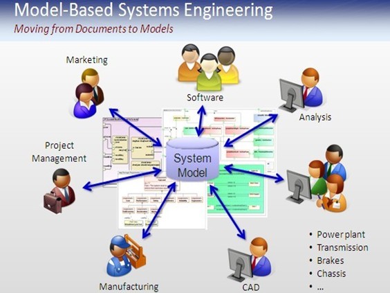
now that we have all these exotic computer based mechanical design
tools. This paper only begins to examine the concept of systems
engineering, what it is, what it is not, and explores how such a concept
might be used for future designs based on requirements.
Background
As a young designer, fresh out of Rutgers University, with my newly
minted BS degree, I worked on a project at Bell Telephone
Laboratories designing the hardware and software for the latest
electronic switching system. This project involved more than 1200
engineers furiously working toward the delivery of an operational
system, within a very tight deadline.
We were organized into development teams, each with about 10-12
engineers, and each working on a piece of the overall project. My team
was developing a portion of the real time operating system. My little
piece was developing the software to scan sensors that detected when
each subscriber required dial tone. Obviously, this was just one of
many steps required to complete a complex call across the network, all
of which would be controlled by duplexed central computers.
Periodically we were visited by representatives of the systems
engineering department, a mysterious group that appeared to be the
design overlords. I didn’t, at the time, understand why they were so
interested in the behavior of my little piece of software. Of course, it
turns out that by analyzing all the “little pieces of software” they were
able to simulate whether the system would even work at all!
It turns out that software design is often developed using systems
engineering, often a requirement for DoD work. Of course, software
appears to be a two dimensional system, as opposed to mechanical
design, which is a multi-dimensional system.
What is it – definition?
Systems Engineering is concerned with the effective design of reliable
systems within cost and time constraints. Systems Engineering applies
an appropriate combination of theories and tools, carried out through
the use of a suitable methodology and a set of system management
procedures, to address real world problems that are often of large
Systems Engineering in CAD
scale and scope. Systems engineering activities vary from
requirements definition or specification to the conceptual and
functional development of systems.
In dealing with the various phases of the system life cycle, the
systems engineer’s perspective is different from that of a product
engineer or technology developer. Whereas the product engineer deals
with details, the systems engineer takes a “top down” perspective
dealing with details only as needed to guarantee successful
implementation. Whereas the product engineer deals with system
internals, the systems engineer also addresses the external view of the
system through the system’s interface to other systems, users, and
managers. A systems engineer needs a unique perspective on the
system and its life cycle.
My design concept
I envision a subsystem where the behavior is specified. A sub-system
that can be designed and tested to satisfy that behavior. One where,
even if the behavior changes, it can re-configure itself to match the
expected behavior. Such behavior can extend beyond design into
manufacturing, deployment, and end-of-lifecycle treatment.
Today’s systems are quite facile at making geometric changes driven
by parameters. But sub-systems are connected using only geometric
mating constraints. If these mating constraints change how is the
corresponding sub-system to react? For instance, suppose two co-
linear shafts connect via a coupling. Suppose one shaft increases in
diameter. How is the coupling or shaft supposed to change? I can
envision embedding each connection with knowledge rules that can
determine this, BUT such rules only work for predetermined changes!
And a rule would have to be written for every connection. Clearly this
is impossible. On the other hand, knowing the characteristics of the
coupling might enable the system to compute such a change. Yet
mechanical systems have no way to describe what happens at each
interface.
Several problems exist in making such a concept operable.
•
No language exists to clearly define what sub systems do.
Consider even the simplistic case of a bolt. We know it has
thickness, thread pitch and depth, and material type. But what
does it do? How does its performance change as its parameters
and characteristics change?
•
Beside geometry, changes include operational characteristics,
geometric sizing and tolerances, external stresses and reactions,
motion behavior, etc. These changes are quite complex to
describe, in fact, often impossible to describe with a regular
language. Think about many systems that can only be described
using non-linear charts, such as RPM vs. power output.
Is this new?
Not really. It is just done manually, if at all.
Who is working on it?
ANSYS – CADOE (behavior and prediction analysis); EDS PLM
Solutions -Slate (requirements); Integrated Chipware – RTM
(requirements management); Telelogic – DOORS (requirements
management)
Discussion topics:
Does the technology exist today?
What would be the benefits?
What tools might be needed?
Sub-system performance definition language?
Considering sub-system interface actions and their interaction
with “connected sub-systems”
Analysis
Kinematics
Predictions tools
About the author
Raymond Kurland is president of TechniCom, Inc, a market research
and consulting firm specializing in the mechanical CAD/CAM market.
TechniCom’s CAD/CAM Vendor program offers many CAD vendors
insight on where the market is and where it is going. Ray authors
many papers and reports on the industry and is the editor of the
TechniCom eMonthly. If hes not here he can be reached at [email protected].
The post Systems Engineering in CAD appeared first on Professionals Resource, CAD Coupons ,Tips ,Deals. from http://www.cad-portal.com/systems-engineering-cad/ What Are The Main Difference’s Between Autocad and Autocad LT ?
“AutoCad is design for 2D as well as 3D drafting by Autodesk whereas AutoCad LT is limited edition with low price having only 2D drafting option. 3D drafting can not be done in AutoCad LT.”
Below are all the latest coupons and discounted price we can offer you on AutoCAD
**CLICK HERE TO GET ** Get the first cloud-based 3D CAD/CAM platform that works on both Mac and PC – just $300/year**CLICK HERE TO GET ** Get two years of Fusion 360 for 50% off + 3 months FREE learning courses from Pluralsight!**CLICK HERE TO GET ** SAVE 20% off a 1-year AutoCAD subscription
The simplest way to explain the difference between these 2 software application programs for style and preparing is the ‘extra D.’ AutoCAD LT uses two-dimensional/2D abilities, whereas AutoCAD brings users three-dimensional/3D power. As you might anticipate, more limited performance in AutoCAD LT also means a lower price.
3D capabilities
The 3D features might be the most substantial difference for some users. If you wish to design in 3D, you have no option however to use the complete variation of AutoCAD. In AutoCAD LT, you can open and view 3D designs created in the complete version of AutoCAD, though you can’t create brand-new ones or edit them, aside from to move, copy, or erase them. The only 3D construction you can do in AutoCAD LT is to use a density (height) residential or commercial property to line work. (In AutoCAD, density implies perpendicular to the drawing airplane; do not puzzle it with width, which applies to objects on the drawing airplane.).
AutoCAD promotion codes and discount coupons here for you to save up to 40% or more.
As well as if you can open 3D models from the full variation in AutoCAD LT, viewing them isn’t really a simple matter. Just a limited variety of preset seeing positions are readily available, unlike in the full variation, where you can turn or orbit around the design to your heart’s material. When you relocate to AutoCAD, you include a entire brand-new measurement. Actually. AutoCAD has 3D drawing capabilities, making it possible for cam views, walkthrough navigation, and model paperwork. One of the cool 3D capabilities is free form design, where you can use robust, mesh, and and solid modeling tools to investigate and refine your concepts. There is likewise a context-sensitive press/pull tool, where you can extrude and offset curves, producing surfaces and solids, and choose numerous items within a single PressPull operation. With the Surface Curve Extraction tool you can draw out isoline curves through a defined point on a surface area or face of a solid to determine the contour lines of any shape. There are a lot of things you can do when you add the 3D capabilities of AutoCAD. When you need to, you can flatten your 3D geometry to 2D for easier paperwork. Over 30 years, Autodesk presented AutoCAD V1 in the winter of 1982 on the DOS os and has continually enhanced and enhanced this world leading CAD bundle to its present kind, version 2016, the 30th significant release. Six years after AutoCAD’s launch, Autodesk launched AutoCAD for Mac with R10 (1988) and it wasn’t till 4 years later that it pertained to MS Windows. So, yes AutoCAD was on the Apple MAC before Windows, but due to the decrease in popularity of the Apple MAC in the late 1980s and early 90s, AutoCAD for MAC was ceased in 1992.
How They Differ
Among the very first and most obvious distinctions between the initial and newer edition programs is that the LT version does not allow for 3D design. There is just no platform offered on the light version for applications having to do with this kind of work. So, if your project includes 3D design or 2D to 3D crossover layouts, you need to use the dad program. The express tools that are available on the full variation are not supported on the LT format. If you’ve never had them, it might mean nothing, but once you have used them it becomes an apparent loss to not have them as a possibility. The abridged program does not allow for the standards inspecting feature that the parent software makes use of. Thus making it tough to abide by industry standards when drafting. The post Difference Between Autocad and Autocad LT appeared first on Professionals Resource, CAD Coupons ,Tips ,Deals. from http://www.cad-portal.com/difference-between-autocad-and-autocad-lt/ What Are The Best CAD Programs For Macs ?
**CLICK HERE TO GET ** Get the first cloud-based 3D CAD/CAM platform that works on both Mac and PC – just $300/year**CLICK HERE TO GET ** Get two years of Fusion 360 for 50% off + 3 months FREE learning courses from Pluralsight!**CLICK HERE TO GET ** SAVE 20% off a 1-year AutoCAD subscription
Before we dive deep into the list of alternatives for Mac-based CAD, there are a couple of things to take into consideration. Windows is a more popular option of OS in some parts of the world, Mac is the more preferred elsewhere. Windows has a really generic method to user-friendliness and Mac is everything about design and feel. For this reason when speaking about any sort of designing or preparing or illustrative work, Mac is undoubtedly a better option because of its natural disposition to style resourcefulness and abundant feel. For this reason the software application listed below include some that are Mac-only and others that are OS-independent.
AutoCAD by Autodesk ( coupons here )
|
ABOUT USCad Portal offers a great range of CAD And Engineering articles ArchivesNo Archives Categories |


 genuine illustration experience.


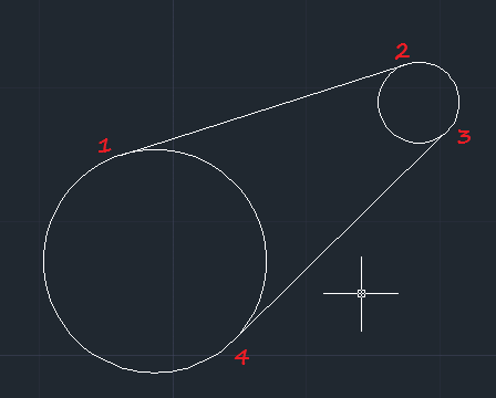

 RSS Feed
